
Heavy Chandelier Installation: Structural Support, Suspension Systems and Architectural Coordination
A large chandelier can become a defining feature of a hotel lobby, ballroom, grand staircase or double-height residence. But before its form, finish and illumination are finalised, one practical question needs to be answered:
How will the building safely support it?
In Indian projects, this question often arises in buildings with reinforced-concrete (RCC) slabs and beams, suspended gypsum ceilings, concealed services and, in existing properties, incomplete structural records. The answer cannot be based on the visible ceiling finish or the chandelier's weight alone.
A successful installation depends on the supporting structure, fixing method, suspension arrangement, electrical coordination, installation access and future maintenance being considered together.
1. Can the ceiling support a heavy chandelier?
The first distinction is between the visible ceiling and the building structure.
A finished ceiling may consist of gypsum board, a suspended metal framework, timber panelling, a metal ceiling system or decorative cladding. These finishes are generally not intended to carry a heavy chandelier independently.
In many Indian commercial and hospitality buildings, the structural system is an RCC frame with slabs, beams and columns. The chandelier's load must be transferred to a suitable structural element through a designed support and connection. The exact arrangement depends on the building's construction and the fixture location.
| Ceiling or structure | What the project team needs to establish |
|---|---|
| RCC slab | Slab thickness, reinforcement, condition, fixing location and structural capacity |
| RCC beam | Beam dimensions, reinforcement, fixing position and suitability of the connection |
| Gypsum or other false ceiling | How the fixture will bypass the ceiling finish and connect to the structure above |
| Structural steel | Member capacity, connection details and suitability of the proposed attachment |
| Timber structure | Member size, condition, connection design and load transfer |
A ceiling's apparent strength or thickness is not proof that it can support a particular chandelier. A general floor loading figure should not be treated as the available capacity for a concentrated suspended load.
For an existing building, especially one without reliable structural drawings, the supporting arrangement must be investigated by a qualified structural engineer. This may involve reviewing available records, site inspection, reinforcement scanning and appropriate material tests.
Non-destructive tests such as rebound hammer and ultrasonic pulse velocity can help assess concrete, but they do not independently establish the load capacity of a structure.
The important principle is to identify the actual structural support and verify the complete load path before finalising the installation.
2. Understand the load path
The load path is the route through which the chandelier's weight is transferred into the building.
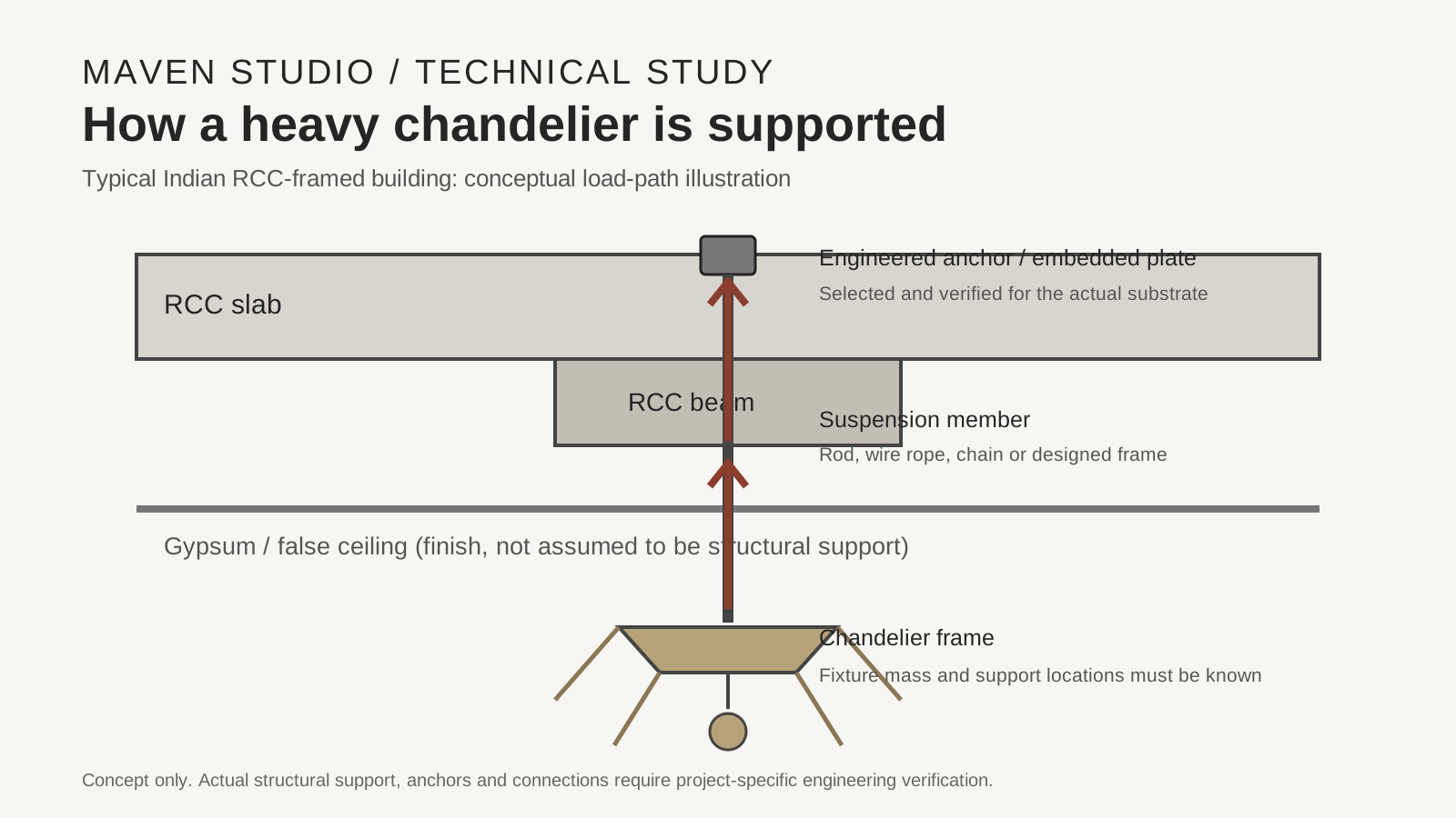
A typical arrangement is:
Chandelier frame → suspension members → upper connection → anchor or support assembly → structural member → building structure
Every part of this chain matters. A strong cable connected to an unsuitable anchor is not a safe installation. A suitable anchor cannot compensate for a structural member that has not been verified.
The fixture's installed mass should be established from its component and material schedule. This should include the main frame, glass, crystal, metalwork, decorative elements, drivers and other components that contribute to the installed mass.
For practical fixture schedules, mass is normally expressed in kilograms (kg). Structural calculations use force, generally expressed in newtons (N) or kilonewtons (kN). For a more detailed explanation of fixture mass estimation, see How to Calculate Chandelier Weight.
The structural engineer must also consider relevant installation conditions and any applicable additional actions, including movement or seismic effects where required by the project.
3. Choosing a suspension system
The suspension system connects the chandelier to its supporting structure. The choice affects appearance, adjustability, rigidity, installation and maintenance.
There is no universally best suspension method. The appropriate system depends on the fixture's mass, geometry, drop length, design intent and supporting arrangement.
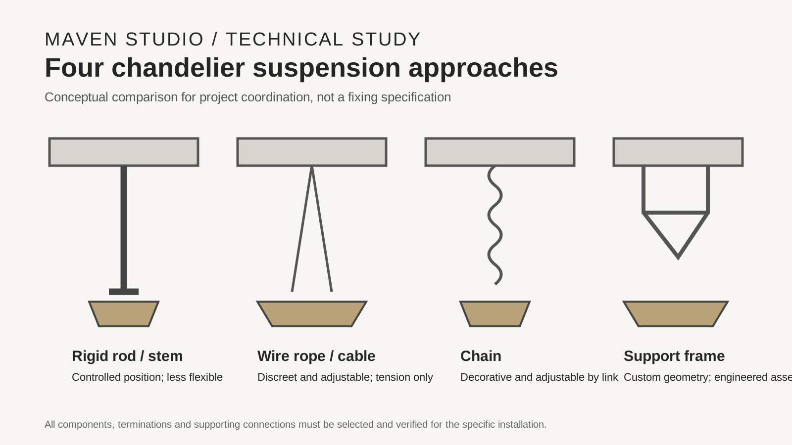
A. Threaded rods and rigid stems
How they work: Steel rods or rigid stems connect the fixture to the upper support, often through threaded connections or purpose-designed brackets.
Advantages
- Provide a rigid and controlled suspension.
- Maintain a defined fixture position and drop.
- Can be integrated into the fixture's structural frame.
- Suitable where precise alignment and a formal appearance are required.
Limitations
- Length adjustments may require fabrication or threaded adjustment provisions.
- Long rods may need additional restraint against lateral movement.
- Alignment and installation tolerances require careful coordination.
- The rod, fittings and upper connections must be designed as a complete system.
Typical applications: Formal chandeliers, large pendants and architectural lighting features where a rigid visual line is desired.
B. Wire rope or aircraft cable
How they work: Flexible steel wire ropes connect the fixture to engineered ceiling fixings using compatible grips, adjusters or proprietary suspension fittings.
Advantages
- Visually discreet, allowing the fixture to appear to float.
- Convenient for adjustable drop lengths when compatible fittings are used.
- Flexible positioning can simplify installation.
- Useful for multiple suspension points and sculptural arrangements.
Limitations
- Wire rope carries tension but does not provide the rigidity of a rod.
- It cannot resist compression or bending in the same way as a rigid member.
- Incorrect termination, adjustment or installation can compromise the system.
- Angled cables can increase the forces acting on the suspension and its fixings.
Typical applications: Contemporary chandeliers, clustered pendants and installations where minimal visible support is preferred.
C. Chains
How they work: A metal chain connects the chandelier to an upper support, usually through suitable links and compatible end connections.
Advantages
- Traditional decorative appearance.
- Drop length can often be adjusted by selecting the appropriate link.
- Can complement industrial, heritage and classical fixture designs.
- Allows some movement rather than behaving as a rigid stem.
Limitations
- More visually prominent than wire rope.
- The chain and every connecting component must be suitable for the application.
- Can twist or swing if the arrangement is not properly considered.
- Fine adjustment may be less convenient than with proprietary cable systems.
Typical applications: Traditional chandeliers and decorative installations where the chain is part of the visual language.
D. Purpose-designed support frames and brackets
Large or unusually shaped chandeliers may need a fabricated support frame, spreader arrangement or structural bracket between the building support and the fixture.
Advantages
- Can distribute loads across selected support locations.
- Can accommodate irregular fixture geometry.
- Allows suspension positions to be coordinated with the fixture's frame and centre of gravity.
- Can provide a practical mounting interface for complex installations.
Limitations
- Requires project-specific design and fabrication.
- Adds coordination between the lighting developer, fabricator and structural engineer.
- Must be checked for its own strength, stiffness, connections and installation requirements.
- May need to be concealed within the ceiling or fixture assembly.
Typical applications: Large chandeliers, double-height installations, complex sculptural fixtures and projects with restricted fixing locations.
A support frame is not automatically a solution to inadequate building capacity. Its connections and the structure receiving the load still require verification.
4. Understanding suspension-point arrangements
A chandelier may be suspended from one central point, two points, three or more distributed points, or a purpose-designed support frame. The arrangement should reflect the fixture's geometry and centre of gravity.
- Single-point suspension: Visually clean and useful for compact fixtures, but the upper connection and fixture frame must accommodate the resulting load and any tendency to rotate.
- Two-point suspension: Can control orientation and distribute the load, but the reactions depend on the fixture's centre of gravity and support spacing.
- Three-point suspension: Can provide a stable arrangement for some geometries, but the actual load at each point still depends on the system.
- Four-point or multi-point suspension: Useful for larger frames and distributed support, but equal load sharing should never be assumed automatically.
For example, a 120 kg chandelier suspended from four points does not necessarily place exactly 30 kg on each point. Differences in cable length, frame stiffness, geometry and installation tolerances can change how the load is distributed.
The suspension arrangement should therefore be developed with the fixture's dimensions, mass and centre of gravity available.
5. Types of anchors and structural fixings
The anchor is the connection between the suspension assembly and the building structure. Selecting one based only on the chandelier's mass is not sufficient.
The substrate, structural condition, fixing location, embedment, edge distances, spacing, installation method and applicable design requirements all influence the choice.
| Fixing type | Typical use | Advantages | Limitations |
|---|---|---|---|
| Cast-in anchor or embedded plate | Planned construction and new-build projects | Can be integrated into the structure during construction | Requires early coordination, accurate positioning and structural detailing |
| Mechanical expansion anchor | Suitable existing concrete substrates | Established installation method and a range of proprietary systems | Performance depends on concrete condition, embedment, edge distance and installation |
| Undercut anchor | Selected concrete applications requiring a mechanical interlock | Provides a defined anchoring mechanism | Requires specific drilling, installation and design procedures |
| Chemical or adhesive anchor | Selected post-installed applications in concrete or masonry | Useful where geometry or fixing conditions make other systems unsuitable | Sensitive to substrate, hole preparation, installation conditions and curing requirements |
| Through-bolt with plate or backing arrangement | Suitable accessible structural assemblies | Can provide a direct mechanical connection | Requires access to the other side and a designed bearing or backing arrangement |
| Engineered steel bracket or support frame | Where a suitable structural connection can be developed | Can accommodate complex geometry or multiple fixing positions | Requires project-specific design, fabrication and verification |
These are categories of fixing systems, not interchangeable products. A mechanical anchor is not automatically suitable for every concrete slab. An adhesive anchor is not automatically preferable because it avoids expansion forces.
The structural engineer should specify or approve the complete fixing arrangement using the relevant manufacturer's technical data and applicable design standards.
For post-installed anchors, important considerations include concrete condition, cracked or uncracked concrete assumptions where relevant, embedment depth, edge distance, spacing, tension and shear actions, and installation quality.
6. What is an RCP, and why does it matter?
An RCP (Reflected Ceiling Plan) is an architectural drawing that represents the ceiling as if it were reflected onto a horizontal plane below. It shows the planned ceiling layout and the location of elements such as lights, access panels, air-conditioning outlets, sprinklers, detectors and other ceiling services.
For a large chandelier, the RCP is an important coordination document. It helps the project team establish:
- The chandelier's exact location and alignment with the room.
- Its relationship to ceiling levels, patterns and architectural features.
- The location of suspension points and ceiling openings.
- The position of electrical supply and control provisions.
- Potential clashes with sprinklers, HVAC outlets, detectors and other services.
An RCP alone is not enough for a complex suspended fixture. It should be read alongside ceiling sections, structural drawings and the chandelier's technical or fabrication drawings. These establish the vertical drop, support locations, fixture dimensions, access requirements and relationship to the structure above.
For large or double-height chandeliers, a coordinated section through the installation is particularly useful. The fixture's mounting details should also be considered during development from reference to manufacturable object. See From Reference Image to Manufacturable Object.
7. Planning for installation and maintenance access
A chandelier should be designed not only for the day it is installed, but also for the years it will remain in service.
A large fixture may require specialist lifting equipment, temporary platforms, scaffolding or a coordinated installation sequence.
The project team should establish:
- Whether the chandelier can be brought into the building in its assembled form.
- Whether it needs to be transported and assembled in sections.
- How the fixture will be lifted to its final position.
- Whether the installation area can accommodate the required access equipment.
- Whether the fixture can be safely reached for cleaning, lamp replacement and maintenance.
- Whether drivers, electrical connections and control equipment remain accessible.
- Whether individual components can be removed without dismantling the entire chandelier.
In hotels and other operational buildings, maintenance access is especially important. A fixture that looks excellent but cannot be safely cleaned or serviced becomes a long-term operational problem.
Where a chandelier is installed over a double-height lobby or staircase, the maintenance strategy should be discussed during design development, not after handover.
8. Who is responsible for what?
A successful installation depends on clear coordination between the design, lighting, structural, electrical and installation teams.
The following is a typical responsibility framework. Actual contractual responsibilities should be confirmed for each project.
| Project participant | Primary responsibility |
|---|---|
| Architect / Interior Designer | Establishes design intent, location, visual alignment, ceiling levels, RCP and architectural coordination |
| Lighting Designer / Consultant | Defines lighting intent, illumination requirements, controls and coordination with the architectural design |
| Lighting Developer / Supplier | Provides fixture dimensions, estimated or final mass, centre of gravity where available, suspension concept, technical drawings and installation information |
| Structural Engineer | Assesses the supporting structure, load path, structural capacity, anchors, brackets and supporting connections |
| Electrical Consultant | Coordinates power supply, earthing, drivers, dimming, controls and electrical requirements |
| Main Contractor / Project Manager | Coordinates site sequencing, trades, access, approvals and installation readiness |
| Specialist Installer | Executes the approved installation and lifting method, follows manufacturer instructions and reports site discrepancies |
The lighting supplier should not independently certify the building's structural capacity. Equally, the structural engineer needs accurate information about the actual fixture and its proposed suspension arrangement.
The two disciplines must work together before the ceiling is closed and the installation reaches site.
9. A practical coordination checklist
Before approving a heavy chandelier for production or installation, the project team should confirm the following.
Fixture information
- Overall dimensions and total installed mass are available.
- Centre of gravity and suspension locations have been identified where necessary.
- Fixture drawings show the mounting and connection details.
- The proposed suspension type and drop length are defined.
Structural coordination
- The actual supporting structural element has been identified.
- Existing drawings and site conditions have been reviewed.
- The structural engineer has assessed the load path and supporting capacity.
- Anchor, bracket and connection details have been specified or approved.
- Relevant movement and seismic requirements have been considered.
Architectural and electrical coordination
- The chandelier is correctly located on the RCP.
- Ceiling sections show the fixture drop and support arrangement.
- Conflicts with HVAC, sprinklers, detectors and other services have been resolved.
- Power supply, earthing, drivers and dimming requirements are coordinated.
- Ceiling openings and access panels are accounted for.
Installation and maintenance
- The transportation and lifting route has been planned.
- Installation access equipment and working space are available.
- Assembly and installation sequence are understood.
- Future cleaning, inspection and maintenance access is practical.
- Final installation and inspection responsibilities are clear.
Conclusion
A heavy chandelier is both a lighting feature and a suspended installation that must be coordinated with the building.
Its success depends on more than the fixture's appearance or the strength of an individual cable or anchor. The supporting structure, load path, suspension system, architectural drawings, electrical provisions, installation sequence and maintenance strategy must work together.
The most effective approach is to involve the relevant professionals early, establish the fixture's technical information before ceiling construction is complete, and ensure that the structural engineer verifies the supporting arrangement.
Good chandelier design does not end with the fixture. It includes how the fixture is supported, installed, accessed and maintained.
Related reading
- How to Calculate Chandelier Weight
- From Reference Image to Manufacturable Object
- Understanding the Metal Casting Process
- Brass vs Kansa in Interior Design
- How Maven develops a lighting project
Further reading and technical references
The following references provide useful background for project teams. The applicable editions of Indian standards and local regulatory requirements should always be confirmed for the specific project.
- Bureau of Indian Standards: National Building Code: National Building Code of India and relevant structural design standards.
- IS 456: Plain and reinforced concrete. Confirm the applicable edition and amendments through BIS.
- IS 800: General construction in steel. Confirm the applicable edition and amendments through BIS.
- IS 875: Design loads for buildings and structures. Confirm the applicable part and current edition through BIS.
- IS 15988: Guidelines for seismic evaluation and strengthening of existing reinforced concrete buildings.
- American Concrete Institute: ACI 318 includes provisions for anchoring to concrete; ACI 562 addresses assessment, repair and rehabilitation of existing concrete structures.
- Manufacturer technical literature: Anchor design, installation instructions, load data and inspection requirements for the specific fixing system selected.
This article is an architectural and project-coordination overview. It is not a structural design specification. The suitability of a particular slab, beam, anchor, suspension member or support frame must be established by qualified project professionals using project-specific information.
Developing a bespoke chandelier for a project? Maven Decoratives works with architects and project teams on fixture development, technical coordination and sourcing for hospitality, commercial and residential spaces. Discuss a project.