
Inside a Metal Foundry: How Casting Works, from Pattern to Finished Component
Casting makes it possible to produce metal components with curves, relief, hollows and details that can be difficult or expensive to machine from solid stock. In decorative lighting and interiors, it may be used for lamp bases, finials, ornamental brackets, ceiling roses, decorative collars, sculptural details and bespoke hardware.
A good casting is not simply a shape taken out of a mould. Its performance depends on the alloy, the mould, how metal fills and solidifies, the finishing process and the inspection requirements agreed before production.

Image: “Casting1.jpg” by Lukas Stavek, licensed under CC BY-SA 3.0. Source and licence details.

1. Choosing the casting process
The right process depends on the component's size, geometry, quantity, alloy, surface requirements and budget.
| Process | How it works | Typical strengths | Points to check |
|---|---|---|---|
| Sand casting | Molten metal is poured into a mould formed from prepared sand. The mould is usually broken to release the part. | Flexible for larger parts, one-off work and relatively low tooling cost. | Surface texture, dimensional variation, parting lines and machining allowance. |
| Gravity or permanent-mould casting | Metal is poured into a reusable metal mould, often called a die. | Can provide repeatability and a better surface than many sand-cast parts. | Tooling cost, geometry limits, mould life and alloy suitability. |
| Pressure die casting | Molten metal is forced into a metal die under pressure. | High production rates and repeatable small-to-medium components, commonly in suitable aluminium or zinc alloys. | Higher tooling investment, design constraints and the need to specify porosity-related requirements. |
| Investment casting (lost wax) | A wax or similar pattern is coated with refractory material; the pattern is removed and metal is poured into the resulting cavity. | Complex forms, fine detail and reduced parting-line constraints. | Pattern and ceramic-shell costs, process control, finishing and achievable tolerances for the actual part. |
For a small run of bespoke brass ornaments, investment casting may be worth evaluating where detail is important. For a large, simple base, sand casting may be more economical. For repeat production of many identical small fittings, die casting may be appropriate. These are starting points, not universal rules: the foundry should confirm process suitability against the drawing and required finish.
2. From pattern to finished component
Step 1: Design and pattern-making
The pattern represents the component and is used to form the mould cavity. Depending on the process and foundry, it may be made from wood, resin, metal, wax or a digitally produced pattern.
The pattern and tooling must account for the alloy's contraction during cooling and for any surfaces that will be machined later. These allowances are not one-size-fits-all values. They depend on the alloy, geometry, process and foundry practice.
For a decorative lighting component, agree the visible dimensions, fixing points, wall thicknesses, concealed joints and finishing allowance before the pattern is approved. A visually attractive model can still be difficult to cast if it contains abrupt thickness changes, thin projections or sections that cannot be fed properly during solidification.
Step 2: Mould and core preparation
In sand casting, prepared sand is packed around the pattern. The pattern is removed, leaving a cavity. Cores may be placed inside the mould to create internal openings or hollow features. Other casting processes use permanent dies or ceramic shells.
The mould also needs a planned route for metal to enter the cavity and for air and gases to escape. Gating, runners, sprues, vents and risers are selected according to the component and process. Risers feed liquid metal into regions that shrink as they solidify.

Image: “EmmotllamentEnArena.png”, a translated diagram based on an earlier sand-moulding illustration, released into the public domain. Source and licence details.

Step 3: Melting and pouring
The foundry selects and melts the specified alloy. Temperature control, melt cleanliness and handling affect the likelihood of inclusions, gas-related defects and incomplete filling. Pouring too cold may contribute to misruns or cold shuts; unsuitable temperature or handling can create other defects.
Do not specify a metal only by its trade name or colour. “Brass”, for example, describes a family of copper-zinc alloys, not one fixed composition. Where material properties matter, specify the applicable grade or agreed chemistry and request traceable documentation appropriate to the order.
Step 4: Solidification and cooling
As metal cools, it contracts. If liquid metal cannot feed a region that is shrinking, a cavity or shrinkage porosity may form. Uneven cooling can also produce residual stresses or distortion. Foundry engineers manage these risks through component design, mould design, feeding, process control and, where required, heat treatment.
Heavy sections connected to thin sections deserve particular attention because they cool at different rates. For decorative parts, this can affect both structural soundness and the final fit of mating components.
Step 5: Shakeout, fettling and machining
After sufficient cooling, the casting is removed from its mould. Sand, gates, runners and risers are removed. This stage is often called shakeout and fettling. The part may then be ground, blasted, filed, machined or polished.
Machining can improve critical dimensions and create accurate threads, seats or mounting faces, but it adds cost and cannot repair every internal defect. Define which faces are functional and which are primarily visual. A hidden mounting face may need tighter dimensional control than a decorative surface, while a polished visible face may need stricter surface acceptance criteria.
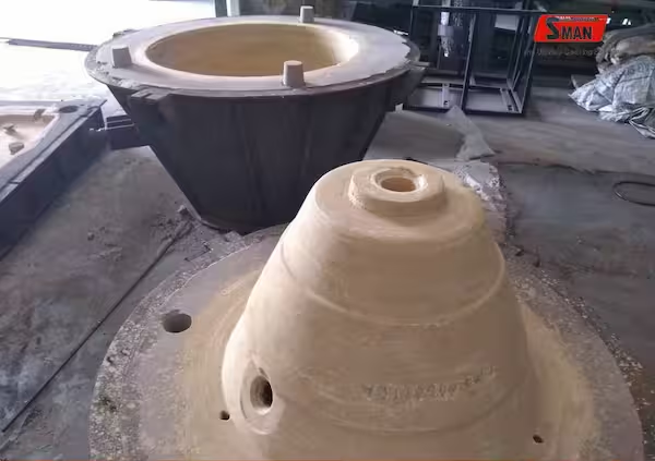
Casting product foundry.jpg” by SMAN ENGINEERS, licensed under CC BY-SA 4.0. Source and licence details

Step 6: Surface finishing and inspection
Depending on the alloy and design, finishing may include mechanical polishing, brushing, plating, lacquer, powder coating or a controlled patina. Surface preparation and compatibility between the base metal and finish matter. A finish can conceal minor visual variations, but it should not be treated as a substitute for checking cracks, porosity or inadequate wall thickness.
Inspection should be agreed before production. It may include visual checks, dimensional measurements, material or chemical verification, hardness or mechanical tests where relevant, and non-destructive testing where the risk justifies it. Not every decorative casting requires every test. The specification should match the part's function and consequences of failure.
3. Common casting defects and why they matter
| Defect | What it may look like or mean | Practical response |
|---|---|---|
| Misrun | The metal has not filled part of the mould. | Review section thickness, flow path, venting and pouring conditions. |
| Cold shut | Two metal fronts meet but do not fuse adequately. | Review filling conditions, geometry and process parameters. |
| Gas porosity or blowholes | Rounded voids or surface holes associated with gas. | Review melt handling, moisture, venting and process control. |
| Shrinkage cavity or porosity | Voids caused by contraction during solidification. | Review feeding, section transitions and solidification design. |
| Inclusions | Non-metallic material or unwanted particles trapped in the casting. | Review melt cleanliness, mould condition and handling. |
| Hot tear or crack | A crack forms while the casting is cooling and constrained. | Review geometry, contraction, mould/core restraint and alloy/process suitability. |
| Warpage | The part distorts from its intended shape. | Review cooling balance, geometry, handling and any heat treatment. |
| Surface roughness or sand inclusion | Surface texture or embedded mould material affects appearance. | Review mould condition and the required finish; agree acceptable limits. |
A small surface pore on a concealed, non-critical area may be judged differently from a pore on a highly polished visible surface or a crack near a suspension point. Acceptance should be defined by location, size, function and finish rather than by a vague instruction such as “good quality”.

Image: “Foundry defect blowhole.jpg” by Orion Lawlor, released into the public domain. The pictured defect was exposed during machining. Source and licence details.

4. Indian foundry practice: what to specify
India has a broad foundry ecosystem, including jobbing foundries for small batches and specialist producers using sand casting, permanent moulds, pressure die casting and investment casting. Actual capability varies by shop. A supplier's stated process alone does not establish that it can meet a particular drawing, alloy, finish or inspection requirement.
For Indian sourcing, the following points help turn a design brief into an inspectable order:
- Material identification: Specify the alloy grade or an agreed chemical composition. Do not rely only on descriptions such as “antique brass”, “bronze finish” or “aluminium metal”.
- Applicable Indian Standard: Where the material and application fall within a relevant BIS standard, identify the standard and edition in the purchase specification. For example, BIS lists IS 617:2024 for aluminium and aluminium-alloy ingots for remelting and castings for general engineering purposes. IS 210:2009 covers grey iron castings. These are examples for their respective material scopes, not blanket standards for all decorative castings.
- Drawing and tolerances: Mark critical dimensions, datums, threaded holes, mounting faces and surfaces requiring machining. State the required tolerance or agree a suitable casting-tolerance system with the foundry.
- Inspection plan: Agree what will be checked, how it will be measured, the sample size or inspection frequency, and what happens if a part fails.
- Traceability: For higher-risk or repeat orders, agree how the batch, material certificate, test results and approved sample will be linked to delivered parts.
- Finish sample: Approve a physical sample or controlled reference for colour, texture, sheen and patina. Photographs alone can be misleading because lighting, screens and polishing direction change perceived colour.
- Packaging and transport: Protect polished or plated surfaces from abrasion, moisture and contact marks. For large or fragile castings, define handling points and packaging before dispatch.
BIS standards are not interchangeable with a generic supplier declaration. Confirm the current edition, scope and any applicable Quality Control Order or certification requirement directly through BIS before relying on a standard for a procurement decision.
5. How European standards fit into the discussion
European standards can be useful references when a project has international consultants, export requirements or a client specification written around EN standards. They should be named accurately and applied only where relevant.
- EN 1559 series addresses technical delivery conditions for castings. It provides a framework for specifying delivery requirements alongside the relevant material standard and purchase agreement.
- EN 1982 covers copper and copper-alloy ingots and castings. It may be relevant when specifying cast copper-alloy components, subject to the exact alloy and product scope.
- EN 1706 specifies aluminium and aluminium-alloy castings, including alloy designation and mechanical-property requirements within its scope.
- ISO 8062 series addresses dimensional and geometrical tolerances for castings, with the applicable part and edition depending on the requirement.
These references are not a claim that European standards are automatically superior to Indian standards. The important questions are whether the standard covers the material and component, whether the contract calls for it, and whether the foundry can demonstrate compliance. Do not assume that an Indian grade and a European grade are identical just because their names appear similar. Check composition, mechanical properties, heat-treatment condition and product form before treating grades as equivalents.
For a project with a European consultant, the drawing or purchase order should state the required standard, edition, alloy designation, tolerance class where applicable, inspection requirements and documentation. If an Indian standard is used instead, any equivalence should be agreed in writing rather than assumed.
6. A practical casting brief for decorative lighting
Before requesting a quotation, provide the foundry or manufacturing partner with:
- A dimensioned drawing or 3D model, including mounting points and critical dimensions.
- The required alloy or a clearly defined material-performance brief.
- The intended use and any loads, vibration, heat or outdoor exposure the component will experience.
- The visible finish, with a physical reference sample where colour or patina is important.
- The expected quantity, repeat-order potential and delivery schedule.
- The inspection and documentation required, including any specified BIS, EN or ISO standard.
- The acceptance criteria for visible surfaces, porosity, repair, machining and dimensional deviation.
For lighting, the casting is often only one part of a larger assembly. Confirm how it joins to sheet metal, tube, threaded inserts, fasteners, wiring routes and suspension hardware. If a component carries the weight of a luminaire, its material and geometry must be assessed for the actual load and installation. Do not rely on appearance alone to establish structural suitability.
Conclusion
Reliable casting begins before the metal is poured. Clear drawings, an appropriate process, a defined alloy, controlled finishing and an agreed inspection plan reduce ambiguity between designer, foundry and installer. Indian and European standards can both provide useful technical frameworks, but only when the correct standard is selected for the material and application and compliance is actually verified.
Technical references
- Bureau of Indian Standards (BIS), IS 617:2024, Aluminium and Aluminium Alloys Ingots for Remelting and Castings for General Engineering Purposes — Specification: BIS document
- BIS, IS 210:2009, Grey Iron Castings — Specification: BIS standard details
- BIS, IS 12880:1989, Guidelines for Controlling Foundry Rejection: BIS standard details
- European standards to verify against the project specification: EN 1559 series (technical delivery conditions for castings), EN 1982 (copper and copper-alloy ingots and castings), EN 1706 (aluminium and aluminium-alloy castings), and ISO 8062 series (dimensional and geometrical tolerances for castings). Check the current edition and scope with the relevant standards body before contractual use.