
How to Calculate Chandelier Weight: Rod Count, Spacing, Structure and Ceiling Loads
From component mass to suspension points, a reliable estimate starts with a component schedule and ends with coordination between the lighting supplier, installer and structural engineer. The worked values below are illustrative and must be replaced by approved drawings and supplier data before fabrication or installation.
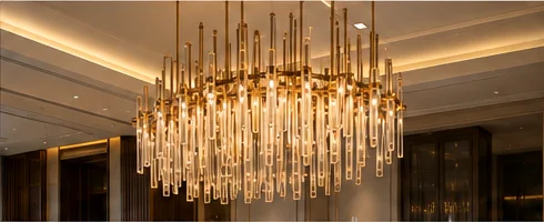
1. Understanding the components
The total fixture mass depends on the number and type of components, their unit mass, and the supporting structure. Break the fixture into its main elements and calculate each part separately.
| Component | Example material or specification | Example total mass |
|---|---|---|
| Glass rod elements | Solid glass, 20 mm × 20 mm section, 1.1 m long | 245 kg for 700 rods at 0.35 kg each |
| Metal frame | Stainless steel or brass structure | 60 kg, illustrative allowance |
| LED strips and drivers | LED strip plus drivers | 35 kg, illustrative allowance |
| Fixings, cables and hardware | Stainless steel / brass components | 10 kg, illustrative allowance |
| Estimated fixture weight | Illustrative total only | Approximately 350 kg |
Do not reuse these example values as a design declaration. Glass geometry, wall thickness, rod length, frame sections, drivers, fasteners and suspension hardware all affect the final mass. Obtain actual unit weights from approved supplier data or weigh representative parts.
2. Worked example: rectangular glass-tube chandelier
Consider a concept measuring 6.8 m × 3.8 m × 1.1 m, with approximately 2,000 glass elements. These dimensions describe the envelope, not the mass by themselves. Calculate the mass of each material and assembly, then add the frame, lighting equipment, wiring, brackets and suspension hardware.
Component mass calculation
For any component:
Total component mass = quantity × unit mass
For a solid rectangular glass rod, a preliminary theoretical mass can be estimated from its volume and the density supplied for the actual glass:
Volume per rod = width × depth × length
Mass per rod = volume per rod × material density
Use consistent units. Convert millimetres to metres before calculating cubic metres. For hollow tubes, subtract the internal volume from the external volume. For profiles, brackets and complex fittings, supplier data or a measured sample is usually more reliable than a simplified geometric estimate.
Keep a schedule with columns for component, material, dimensions, quantity, unit mass, total mass, data source and status (estimated or confirmed). Sum the rows only after checking that no item has been omitted or counted twice.
3. Rod count, spacing and layout
Rod count must come from the layout drawing, not from the overall fixture dimensions alone. For a regular grid, a first-pass count along one axis can be estimated from the usable span and centre-to-centre pitch, then checked against edge offsets and the actual drawing. The final count is the number of positions shown in the approved layout.
For example, a pendant with a nominal diameter of 1,800 mm and a drop of 1,200 mm might use 72 rods with nominal spacing in the 60–75 mm range. These are concept-stage values only. Confirm whether the spacing is measured centre-to-centre, whether the outer ring has a different pitch, and how the rods connect to the frame. Record rod lengths and quantities by group if the design has multiple tiers.
4. Ceiling load and suspension
Fixture mass is not the same as the design load at each fixing. Do not divide total mass by the number of suspension points and assume the result is the final support load. Actual reactions depend on centre of gravity, support geometry, frame stiffness, load distribution, dynamic effects and installation tolerances.
Before installation, coordinate the following:
- Suspension points: locations, connection details and the load assigned to each point by the responsible designer.
- Ceiling structure: the actual supporting structure, not only the decorative ceiling or false ceiling.
- Safety factors and applicable requirements: to be determined by the qualified structural engineer and relevant project standards.
- Coordination: access for installation, driver locations, wiring routes, maintenance and replacement of components.
The ceiling, anchors, suspension members and fixture frame must be verified as a complete load path by the responsible structural engineer or qualified installation specialist. This article is a preliminary estimation guide, not a structural design approval.
5. Key takeaways
- Calculate component mass first, then sum the complete fixture.
- Confirm rod count and spacing against the approved layout drawing.
- Keep estimated values distinct from supplier-confirmed masses.
- Verify the ceiling and suspension system independently of the fixture-weight estimate.
- Provide the installation team with approved drawings, final mass, centre-of-gravity information where relevant, connection details and maintenance access requirements.
Related reading
- Heavy CHandelier Installation
- From Reference Image to Manufacturable Object
- How Maven develops a lighting project
Further reading
- American Institute of Steel Construction (AISC) for structural steel design resources.
- Glass and Glazing Federation for glass-related technical guidance.
- Illuminating Engineering Society for lighting design and application resources.
Use standards and guidance appropriate to the project jurisdiction and actual materials. A qualified engineer must verify the final support design and installation details.