
A reference image can communicate the visual intent of a chandelier: its silhouette, rhythm, finish, glow and relationship to a room. It rarely tells a fabricator enough to build it safely or repeatably. A photograph does not reliably reveal hidden joints, material grades, wall thicknesses, driver locations, suspension details, actual dimensions or the structure above the ceiling.
The task is therefore not simply to copy an image. It is to convert visual evidence into a controlled design with explicit assumptions, measurable geometry, verified materials, coordinated interfaces and a traceable manufacturing package.
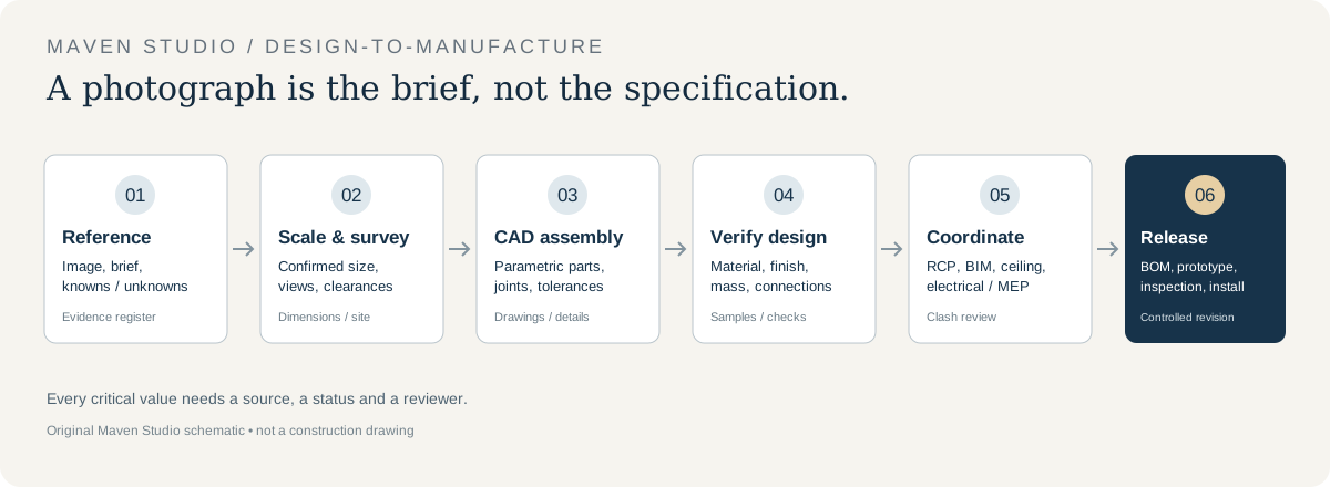
Figure 1. Maven Studio workflow. The image is an input to design development, not proof of dimensions or construction.
1. Start by separating evidence from assumptions
Before modelling, make a reference register. Record what the image clearly shows, what can be estimated, and what remains unknown. Assign each value a confidence level and a verification method.
| Information | What a single image can suggest | What is needed to confirm it |
|---|---|---|
| Overall form | Silhouette, symmetry, approximate proportions | Front, side and top views; site envelope; client approval |
| Dimensions | Ratios and relative spacing if a known scale is visible | One known dimension, measured object, dimensioned sketch or site survey |
| Material | Visual appearance and likely material family | Finish sample, material specification, supplier confirmation or test |
| Section / thickness | Usually not visible | Detail drawing, sample inspection or engineering decision |
| Fixings | Possible suspension points and visible joints | Connection details, access requirements and load-path review |
| Light source | Apparent glow, direction and visual effect | LED/lampholder data, driver specification, photometry and thermal review |
| Weight | Cannot be reliably read from appearance | Component schedule, material densities, actual unit masses and prototype weighing |
Important: do not present inferred values as measured facts. Label them assumed, provisional or to be confirmed. This is especially important when a design is priced from a photograph before a site visit or engineering review.
2. Establish scale before claiming dimensions
A perspective photograph distorts apparent size. Objects closer to the camera look larger; a lens may introduce distortion; and the visible front edge may conceal depth. A single unscaled image generally cannot determine absolute dimensions uniquely.
If a reliable reference length is visible in approximately the same plane as the feature being measured, a first-pass scale estimate is possible:
For a rough first-pass estimate:
image scale = known real length / known length in image pixels
estimated feature length = feature length in pixels × image scale
This is a rough estimate, not a production dimension. It becomes unreliable when the known reference and target sit at different depths or orientations. For a bespoke fixture, request at least a front elevation, side elevation, plan view, one confirmed dimension and the intended ceiling / mounting condition. A physical sample or a series of photographs from multiple angles can reduce ambiguity.
Example: proportion versus size
Suppose a reference image suggests that a chandelier is about 1.6 times as wide as it is deep. That ratio may be useful for a concept model. It does not prove that the finished fixture should be 1,600 mm wide and 1,000 mm deep. Those absolute dimensions must come from the room, the reflected ceiling plan (RCP), clearances, the client's brief and a verified reference dimension.
3. Use photogrammetry carefully
Photogrammetry reconstructs geometry from overlapping photographs taken from multiple viewpoints. It is useful for irregular decorative objects, existing components or a physical prototype when the object can be photographed clearly from all around. It is not magic image-to-CAD: reflective brass, transparent glass, glossy black surfaces, repeated rods and featureless areas can make reconstruction difficult. Scale must also be established using a known dimension or control scale.
For photogrammetry, capture overlapping views around the object, keep focus and exposure consistent, avoid changing the object between frames, and include a scale reference. The resulting mesh may describe the visible surface but normally still needs cleanup and conversion into editable, manufacturing-intent CAD geometry. A triangulated mesh is not automatically a parametric solid, a tolerance-controlled part or a production drawing.
For reference, Wikimedia Commons hosts a CC BY-SA 4.0 illustration showing a camera array and the principle of multi-view reconstruction: Camera Array Photogrammetry.svg. Credit: Californiascott1, CC BY-SA 4.0. Review the file page before reuse and retain attribution and licence details.


Source image: “Camera Array Photogrammetry.svg” by Californiascott1, licensed CC BY-SA 4.0 via Wikimedia Commons. The external image is included as an open-licence reference; if your production site blocks remote SVGs, download the file from the linked Commons page, verify the licence metadata, and serve an optimised local copy with attribution.
4. Convert the form into a parametric CAD model
Build the model from a small number of meaningful parameters rather than tracing every pixel. Typical parameters include overall width and height, canopy diameter, centreline, ring diameters, rod length, rod pitch, glass size, mounting offsets and cable drop. A change to one controlled parameter should update related geometry predictably.
Use a staged model:
- Envelope model: overall dimensions, ceiling clearance, visual proportions and service access.
- Assembly model: major parts, subassemblies, interfaces, fixing positions and installation sequence.
- Manufacturing model: actual profiles, wall thicknesses, bend radii, holes, threads, welds, machining allowances and tolerances.
- Drawing package: dimensioned elevations, plan, sections, exploded view, connection details, finish notes and revision status.
A rendered model communicates appearance; it does not replace a dimensioned drawing. Define critical dimensions and tolerances explicitly. For production, the drawing and model must make clear which dimensions control fit, alignment, replaceability and assembly. ISO 129-1 gives general principles for presenting dimensions and associated tolerances; ASME Y14.5 is a recognised reference for geometric dimensioning and tolerancing where that system is specified.
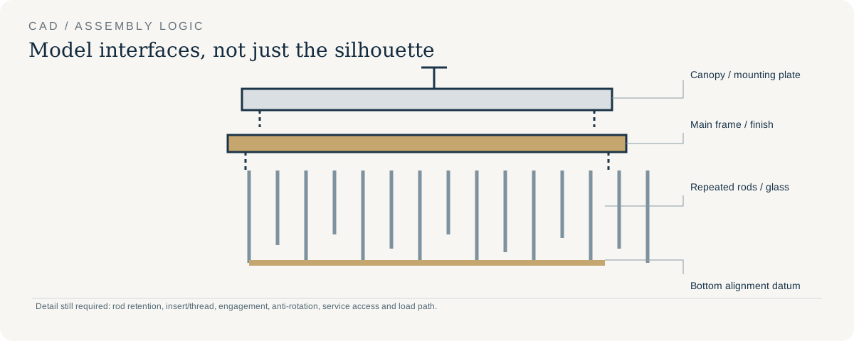
Figure 2. Original schematic for this article, not a construction drawing. Actual dimensions and connection details must be developed for each fixture.
5. Select materials from performance, not appearance alone
A gold-coloured surface could be brass, plated steel, aluminium with a coating, or another substrate with a decorative finish. The image cannot reliably identify the alloy, grade, thickness, joining method or coating system. Record the substrate and finish separately.
| Component | Design questions to resolve | Evidence to request |
|---|---|---|
| Main frame | Stiffness, span, deflection, corrosion, weldability and finish | Material grade, section size, joint details and finish specification |
| Rods / tubes | Diameter, wall thickness, straightness, cut length and end connection | Supplier data, section drawing, tolerance and actual mass per length |
| Glass / crystal | Type, thickness, edge treatment, hole detail and breakage risk | Glass specification, sample, dimensions and approved fixing method |
| Cast or machined parts | Alloy, porosity risk, machining datum and repeatability | Grade, process route, machining drawing and inspection plan |
| LED / driver | Voltage, power, dimming protocol, heat, access and replacement | Datasheets, wiring diagram, photometry and service clearance |
| Finish | Colour, gloss, texture, corrosion resistance, cleaning method | Approved physical sample, process description and acceptance criteria |
| Suspension / canopy | Load path, adjustability, access and ceiling interface | Connection details, rated hardware data and structural approval |
Finish samples should be approved under relevant lighting conditions. A colour seen on a screen or in a warm photograph is not a dependable finish specification. For repeat production, retain a signed sample or documented master and define acceptable variation.
6. Estimate mass component by component
Do not estimate a fixture's weight from its visual size alone. Break the assembly into parts, calculate or obtain the mass of each, then total the values. For a uniform solid part, mass is density multiplied by volume. For a tube, use the difference between outer and inner volumes. For purchased parts, supplier mass or a measured sample is usually preferable to a rough geometric estimate.
mass = density × volume
m = ρV
For a straight hollow circular tube of length (L), outer diameter (D_o), and inner diameter (D_i):
For a straight hollow circular tube:
volume = (π × length / 4) × (outer diameter² − inner diameter²)
V = (πL / 4) × (Do² − Di²)
Use consistent units. If density is in kg/m³, calculate volume in m³ to obtain mass in kg. Add allowances for connectors, fasteners, drivers, wiring, canopies, decorative elements and other hardware. Avoid double-counting parts included in a supplier's assembly mass.
Worked estimate: illustrative only
Assume a fixture contains 48 solid glass rods, each 0.60 m long, with a nominal circular-equivalent diameter of 12 mm. Treating each rod as a solid cylinder gives a preliminary volume per rod of approximately 0.0000679 m³. If a verified material density of 2,500 kg/m³ is used for the example, the theoretical mass is approximately 0.170 kg per rod, or 8.15 kg for 48 rods. This is only a simplified estimate: real glass sections may not be circular, and end fittings, tolerances and actual glass type change the result. Replace assumptions with supplier data and weigh a representative sample before freezing the BOM.
| Mass line | Calculation / source | Status |
|---|---|---|
| Glass rods | Count × verified unit mass | Confirm from supplier or sample |
| Metal frame | CAD volume × material density, or weighed prototype | Preliminary until joints and sections are final |
| Castings / brackets | Supplier data or part mass | Confirm material and finish allowance |
| LEDs, drivers and wiring | Datasheets and actual configuration | Confirm exact model and quantity |
| Fasteners, canopy and suspension hardware | Supplier masses / weighed parts | Include all load-bearing hardware |
| Total fixture mass | Sum of all component masses | Reconcile with prototype weighing |
The fixture's own mass is not the same as the load that the building structure must be designed to resist. Dynamic effects, installation conditions, the number and geometry of suspension points, eccentricity and applicable design factors require qualified engineering review. Do not use an article calculation as approval of a ceiling anchor or support frame.
7. Design joints, fittings and assembly access
Connection design is often where an attractive reference becomes difficult to manufacture. A rod may appear to enter a frame, but the image cannot show whether it is threaded, bonded, clamped, welded, pinned or held by a concealed insert. Every interface needs a deliberate construction method.
For each connection, define:
- mating part IDs and material thicknesses;
- thread, insert, pin, clamp or adhesive specification where applicable;
- engagement length and access for tools;
- allowable alignment and angular variation;
- how the joint transfers load and prevents loosening;
- whether the joint is visible, concealed, serviceable or replaceable;
- assembly order and protection of finished surfaces.
Prototype high-risk joints before committing to full production. A small physical mock-up can reveal access, tolerance stack-up, glare, reflections, glass clashes and installation problems that a hero render may conceal.
8. Coordinate the fixture with the RCP and site conditions
The reflected ceiling plan is the coordination drawing that locates the fixture in the actual room. It should establish the fixture tag, centre point, orientation, dimensions, mounting height or drop, ceiling level, nearby lights, diffusers, sprinklers, access panels and other relevant services. Check the fixture against the latest architectural ceiling, structural and MEP drawings, not an old presentation plan.
For a suspended chandelier, verify at minimum:
- finished floor to ceiling and ceiling void / structural support levels;
- bottom-of-fixture elevation and required head clearance;
- canopy location and the actual structural fixing point;
- clashes with beams, ducts, sprinklers, detectors, curtains and access panels;
- cable / rod drop, levelling adjustment and installation access;
- driver location, ventilation, maintenance access and cable route;
- switching, dimming, circuiting and emergency requirements where applicable.
A decorative fixture may be visually centred in the room but not centred on the ceiling support available above it. If the desired location conflicts with a beam or service, resolve it with the architect, electrical consultant, MEP team and structural engineer before production.
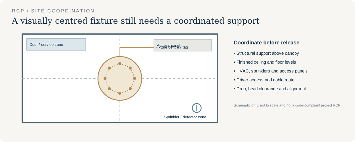
Figure 3. Coordination schematic only. It is not a project RCP and does not define required clearances or code compliance.
9. Build the BIM object to serve coordination
A BIM family or object should carry the information needed by the project team, not just a detailed 3D shape. In Revit, lighting fixture families can contain identity data, electrical loads and photometric parameters; parameters such as manufacturer, model, wattage, and an IES photometric web file may be relevant when verified data is available.
Useful fixture parameters include:
| Parameter group | Typical fields |
|---|---|
| Identification | Fixture tag, type mark, manufacturer / vendor, model, revision, URL |
| Geometry | Width, depth, height, canopy size, drop, mounting plane, service envelope |
| Weight | Estimated fixture mass, source of value, revision / confidence status |
| Electrical | Voltage, wattage, driver model, dimming protocol, connection point |
| Lighting | CCT, CRI, lumen output, beam / distribution data, verified IES file if available |
| Installation | Suspension points, mounting method, access zones, structural coordination note |
| Procurement | Finish code, approved sample reference, BOM / schedule key, lead-time note if known |
Use simplified geometry when detailed internal parts do not help coordination. Keep the BIM object's dimensions and data consistent with the approved CAD model and schedule. Do not invent photometric data or put a placeholder weight into the project as if it were verified. Autodesk's documentation explains lighting-fixture and light-source parameters: Parameters for Lighting Fixtures and Light Sources.
10. Generate the BOM from the controlled model
The bill of materials (BOM) connects design intent to purchasing, production, quality control and assembly. Each line should have a unique part number, description, material / grade, finish, dimensions or drawing reference, quantity per fixture, unit, supplier / make where approved, and revision. Separate fabricated parts from bought-out components and consumables. Define whether the quantity is per fixture, per room or per project.
A practical BOM structure:
| Item | Part ID | Description | Material / finish | Qty per fixture | Unit mass | Drawing / spec | Status |
|---|---|---|---|---|---|---|---|
| 1 | ASM-001 | Main frame assembly | Grade and finish to be specified | 1 | To verify | Assembly drawing | Concept |
| 2 | GL-001 | Glass rod, cut to length | Glass type and edge finish to be specified | 48 | Supplier value required | Detail drawing | Provisional |
| 3 | LED-001 | LED module / strip | Exact model and CCT to be approved | As designed | Datasheet | Electrical schedule | Provisional |
| 4 | DRV-001 | LED driver | Exact voltage, power and dimming type | As designed | Datasheet | Wiring diagram | Provisional |
| 5 | FIX-001 | Suspension and fixing kit | Rated system to be selected | As designed | Supplier value | Connection detail | Engineering review |
These rows are an example of the information structure, not a finished purchasing BOM. Do not issue it for procurement until quantities, specifications, revision, supplier and approvals are resolved. The BOM, drawing, CAD model and BIM schedule should share the same part IDs and revision logic.
11. Verify with a prototype and controlled release
Before the production release, hold a design review against a checklist rather than relying on visual approval alone.
- Geometry: overall envelope, dimensions, symmetry, rod spacing, drops and mounting points checked against approved drawings.
- Material / finish: substrate, finish process, colour and gloss sample approved; cleaning method and acceptance criteria documented.
- Mass: component schedule reconciled; sample or prototype weighed; final mass communicated to the responsible structural reviewer.
- Electrical / thermal: driver, LED, wiring, dimming, ventilation, access and serviceability verified by the responsible specialist.
- Assembly: joint access, fasteners, installation sequence, packaging and replaceable parts tested.
- Site coordination: RCP, support location, clearances, cable route and ceiling levels checked against current drawings.
- Documentation: CAD, drawings, BOM, BIM object, finish schedule and installation instructions have matching revision identifiers.
A first-off prototype or representative mock-up is especially valuable for complex bespoke lighting. Check actual fit, finish, alignment, light appearance, service access and installation method before authorising a batch.
12. The deliverable set: what turns a picture into a buildable product?
| Deliverable | Purpose | Typical release gate |
|---|---|---|
| Reference / assumption register | Separates known facts from inference | Concept approval |
| Dimensioned GA drawing | Establishes overall envelope and interfaces | Design freeze |
| 3D CAD assembly and part models | Defines geometry and construction | Design / manufacturing review |
| Connection and manufacturing details | Defines joints, tolerances and processes | Production release |
| Material and finish schedule | Controls substrate, finish and approved samples | Sample approval |
| Mass estimate and load-path note | Supports coordination and engineering review | Before installation design is frozen |
| RCP / ceiling coordination mark-up | Confirms position and site interfaces | Consultant coordination |
| BIM family / object | Carries coordinated geometry and verified data | BIM coordination review |
| BOM and electrical schedule | Enables purchasing, assembly and inspection | Procurement release |
| Prototype / inspection record | Confirms that the built object matches intent | Batch approval |
| Installation and maintenance sheet | Enables safe installation and future service | Handover |
Conclusion
The reference image starts the process; it does not finish it. A reliable translation into a bespoke lighting fixture moves from evidence and assumptions to scaled geometry, parametric CAD, specified materials, component-level mass estimates, engineered connections, RCP and BIM coordination, a controlled BOM, prototype validation and installation documentation.
The key discipline is traceability: every important dimension, material, weight, finish and connection should have a source, a responsible reviewer and a revision. Where the photograph cannot provide the answer, record the unknown and resolve it before the design is treated as manufacturable.
Related reading
- Heavy CHandelier Installation
- How to Calculate Chandelier Weight
- How Maven develops a lighting project
Further reading and references
- Autodesk, Parameters for Lighting Fixtures and Light Sources. Official documentation for lighting fixture identity, electrical and photometric parameters.
- Autodesk, Creating lighting fixture families in Revit. Official learning module on model geometry, shared parameters and photometric files.
- ISO, ISO 129-1:2018: Technical product documentation, presentation of dimensions and tolerances. General principles for dimension presentation.
- ASME, Dimensioning and Tolerancing, Y14.5. Overview of geometric dimensioning and tolerancing.
- McGill University, Working Drawings and Assemblies. Drawing and BOM conventions.
- Wikimedia Commons, Camera Array Photogrammetry.svg. Californiascott1, CC BY-SA 4.0. Check the licence page and include attribution when reusing the source illustration.
- Wikimedia Commons, Design for a Chandelier, 19th century. Metropolitan Museum of Art object image; verify the file's reuse status and applicable terms before republishing.
